Let’s see Customizing UDI Wizard with UDI Designer Using SCCM. In part 1 of this series on User-Driven Installation (UDI), I explained how you can integrate MDT with SCCM | Configuration Manager and MEMCM to create a User-Driven Installation OSD task sequence for a better end-user experience.
If you missed it, I recommend starting from Configure User-Driven Installation UDI Using ConfigMgr | SCCM. Since we have successfully created the Task Sequence, the next step is to customize the UDI wizard to Deploy the Image.
The UDI Wizard is the UI that allows customization of the deployment process based on configuration settings made in the wizard. The configuration settings are used to modify the task sequence variables and unattended installation files used in the operating system and application deployment process.
The UDI Wizard configuration file controls the wizard pages displayed in the UDI Wizard and the controls active for each wizard page.
UDI Deployment Process Components
- UDI Wizard
- UDI Wizard Designer
- UDI Wizard Configuration File
- UDI Task Sequences
Why Use UDI Designer?
The UDI Designer customises the UDI Wizard configuration file (UDIWizard_Config.xml), which the UDI Wizard (OSDSetupWizard.exe) reads at runtime. The Pages element in the UDI Wizard configuration file contains a list of pages, with a separate Page element for each wizard page.
You can use the UDI Wizard Designer to:
- Determine the wizard pages that are displayed in the UDI Wizard.
- Determine the sequence of the wizard pages that are displayed in the UDI Wizard.
- Configure default values for controls on the wizard pages.
- Enable or disable individual controls on the wizard pages.
Can We customize only the MDT wizard with UDI Wizard Designer?
The UDI Designer is only for Configuration Manager. The MDT Lite Touch wizard is just an HTA page that includes scripts, web services, and other customization items.
Customizing UDI Wizard Configuration File
The default UDI Wizard configuration file is named UDIWizard_Config.xml and is stored in the Scripts folder in the MDT files package.
Customize the UDI Wizard configuration file for the reference computer.
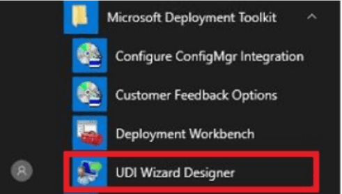
Click Start, Under All Programs, Expand Microsoft Deployment Toolkit and then start UDI Wizard Designer Run as administrator.
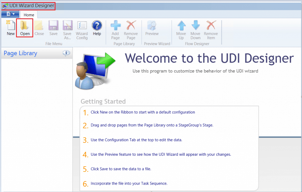
The UDI Wizard Designer starts. On the Home tab, click Open.
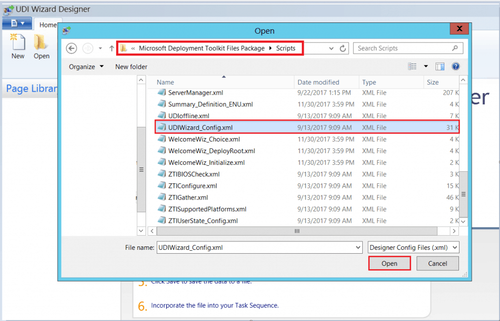
In the Open dialog box, either type directly the MDT Files Package source or Browse the path, and then locate the “UDIWizard_Config.xml” file that resides in the MDT Package\Scripts folder that was created when you ran the Create Microsoft Deployment Task Sequence Wizard earlier in the process. Click Open.
Important – Do not directly modify the UDI Wizard configuration file. Instead, use the appropriate wizard page editors in the UDI Wizard Designer.
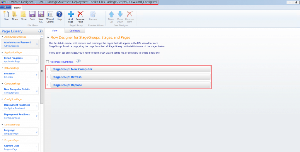
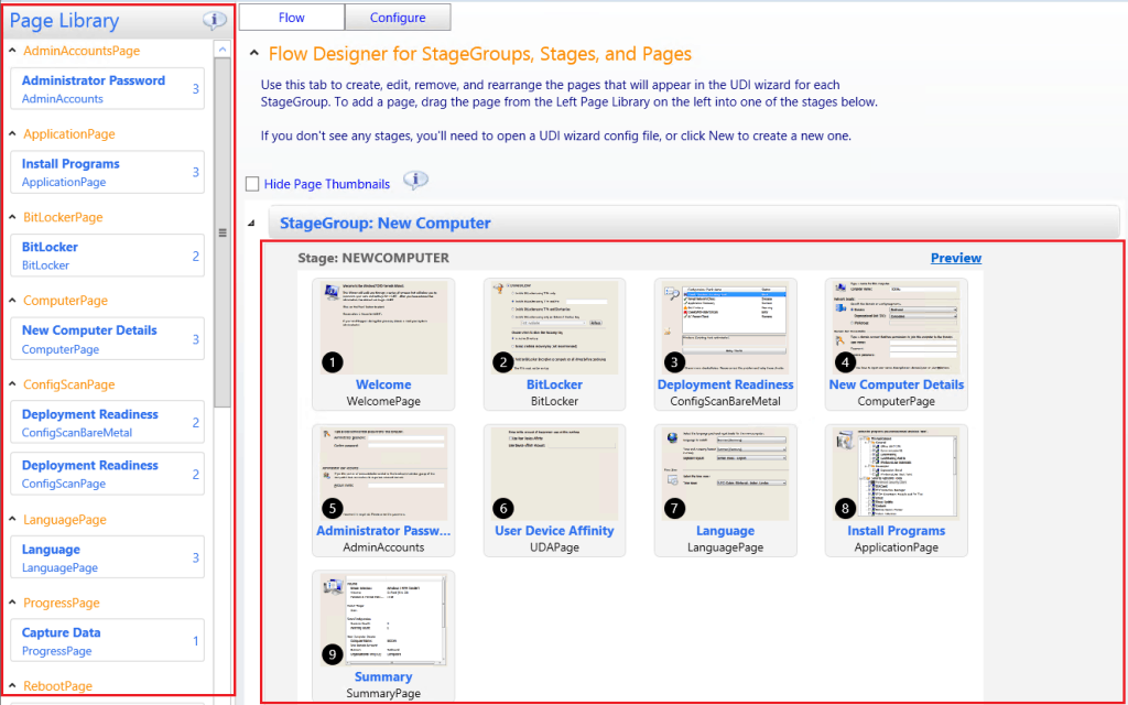
The details pane contains a list of the stage groups and stages that the UDI Wizard configuration file supports. Each stage group listed in the details pane is used in one or more of the following MDT deployment scenarios.
- New Computer
- Refresh Computer
- Replace Computer
Click on the New Computer Details page under the Page Library Pane. By default, the new computer stage has 11 different pages. If required, we can customize them as needed.
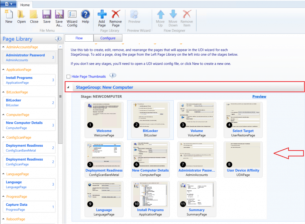
- Double-click on the selected wizard page to open and customize them if needed.
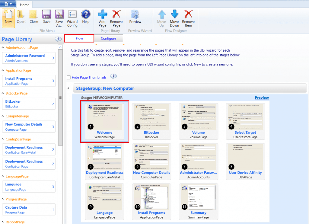
By default, all controls are enabled on all wizard pages. Using the UDI Wizard Designer, you can disable individual controls on each wizard page to prevent users from entering information using those controls. The UDI Wizard designer has a button that displays the following status:
Unlocked – This status indicates that the control is enabled and users can enter information using the wizard.
Locked – This status indicates that the control is disabled and users cannot enter information.
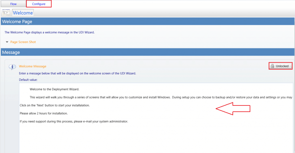
Tip – Remember to save the UDI Wizard configuration file after making any changes.
- Expand Computer Name Settings.
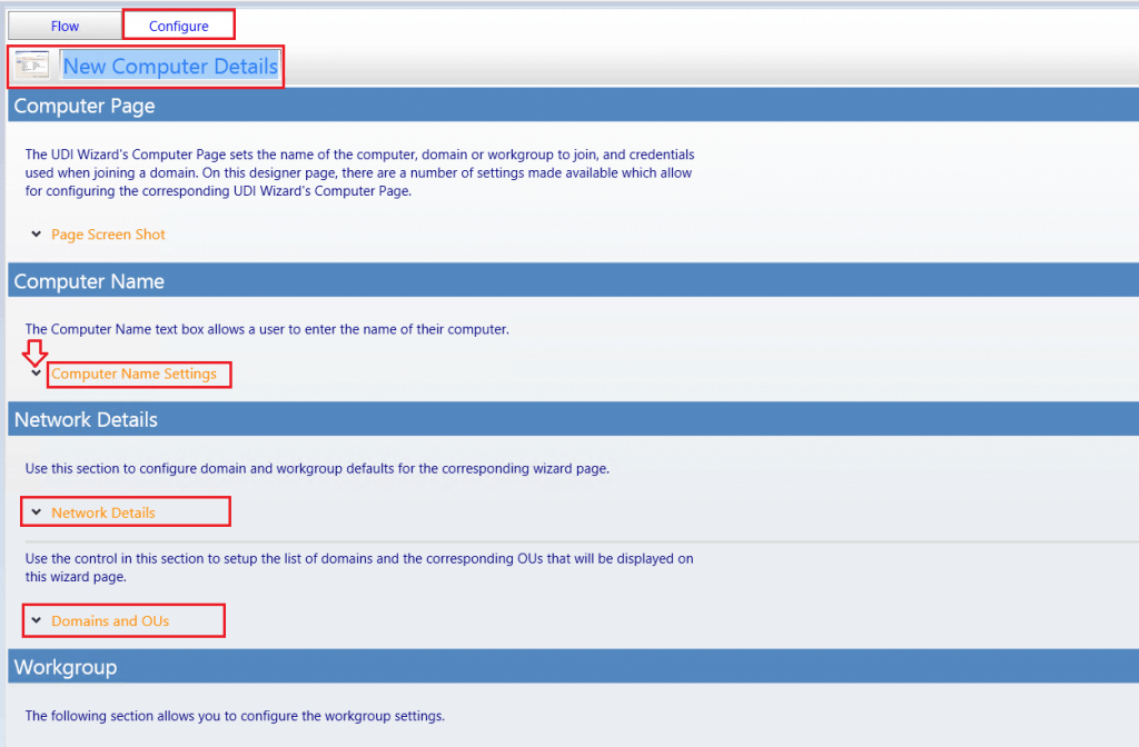
Under Network Details, expand Network Details in Domain or Workgroup Radio Buttons. I selected Domain and provided the Default value in Domain Combo Box.
The status changed to Locked, which prevents users from changing this option in the UDI Wizard.
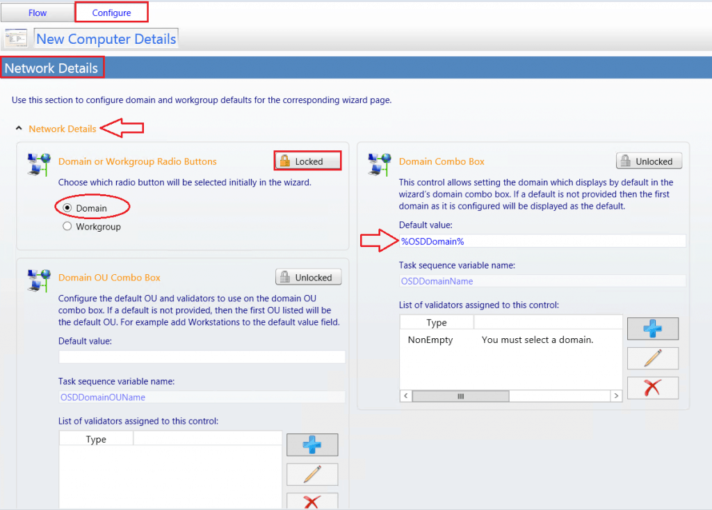
Expand Domains and OUs, and then click Add Domain. The Create or Edit Domain Information dialog box appears. In the Create or Edit Domain Information dialog box, in Domain Name type <Your Organization or Test Domain Name>. In Friendly Name, type <Any Name that wants to appear> and click OK.
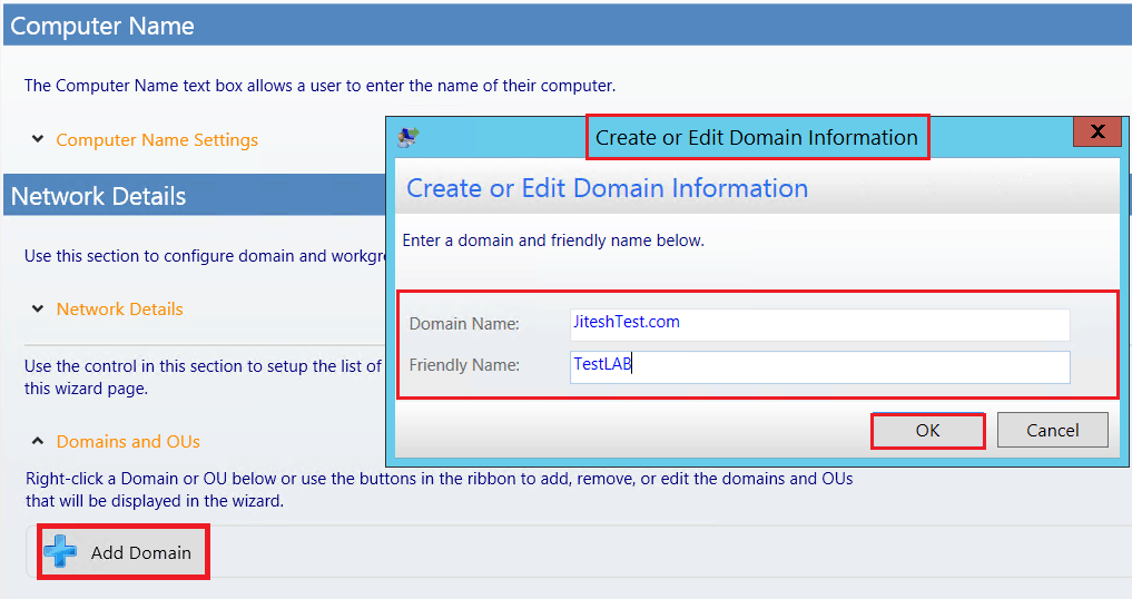
Right-click a Domain or OU to add, remove, or edit the domain and OUs that will be displayed. You could also add OUs manually, as shown below.

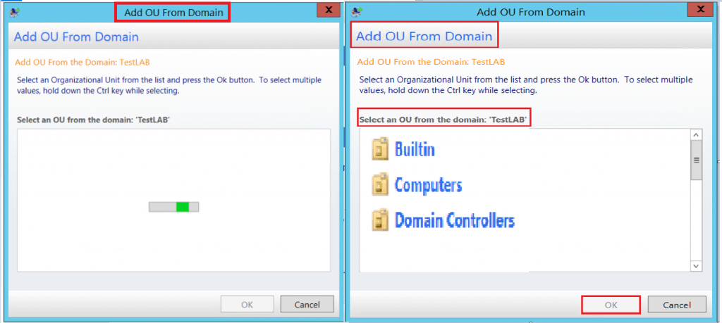
In the Add OU From Domain window, Select an OU from the list and click OK. The selected OUs will appear under Domain Name.
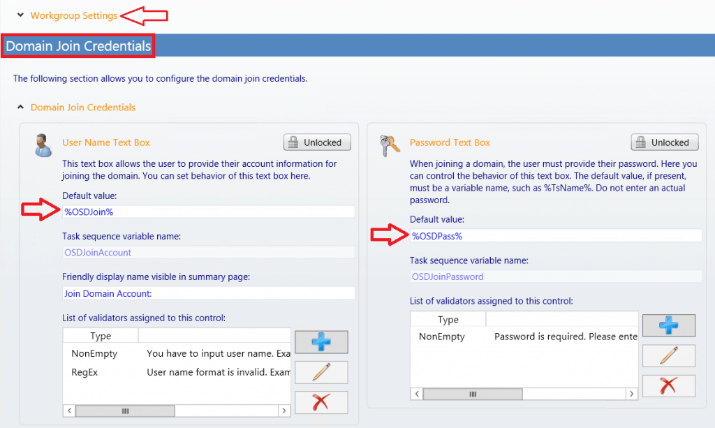
Expand Domain Join Credentials to configure
Under the User Name Text Box, provide the Default value to account for joining the domain. Under the Password Text Box, provide the Default value to the account password for joining the domain.
Skip or Remove UDI Wizard Panes
To remove a wizard page from a stage
In the UDI Wizard Designer console, expand the stage in the details pane and click the wizard page that you want to remove.
On the Home tab, click Remove-Item. The Delete Item Confirmation dialog box appears. In the Delete Item Confirmation dialog box, click Yes.
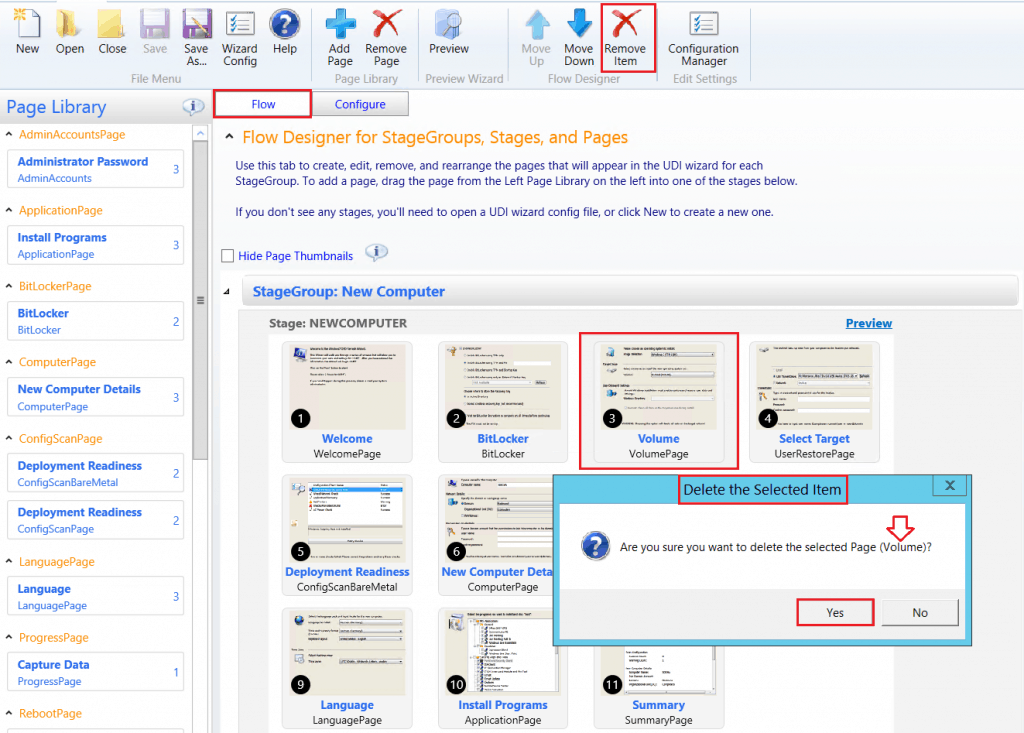
In the details pane, the wizard page is removed from the stage.
Note – You can remove wizard pages within a stage. Removing a wizard page from a stage does not remove a wizard page from the Page Library pane.
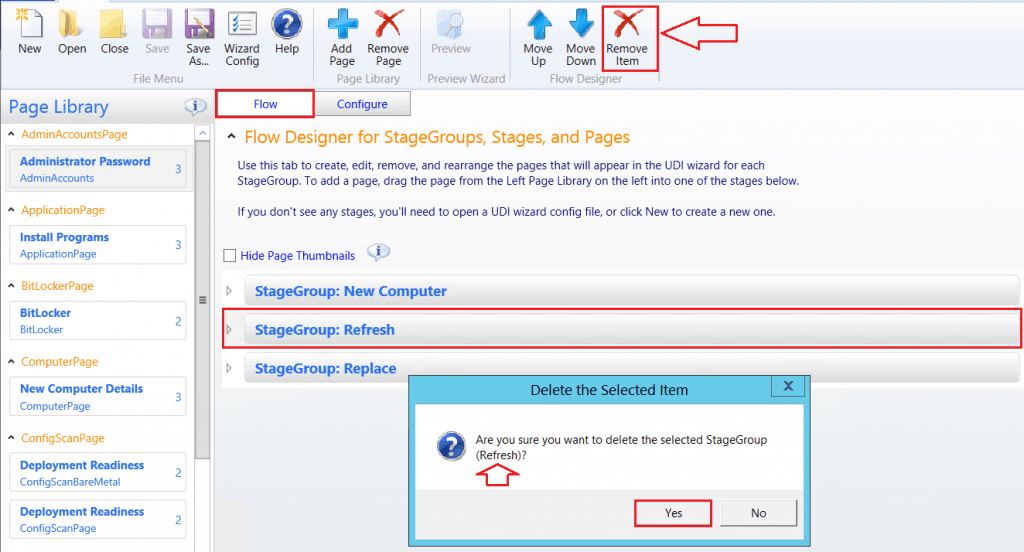
To remove a StageGroup
Click on StageGroup, which you want to remove. Click Remove-Item. The Delete Item Confirmation dialog box appears. In the Delete Item Confirmation dialog box, click Yes.
Change the Wizard Page Sequence Flow
The UDI Wizard displays a sequence of wizard pages used to collect the necessary information to complete the operating system and application deployment. You can see the sequence of wizard pages within a stage.
To change the wizard page sequence flow within a stage
In the UDI Wizard Designer console, in the details pane, expand the stage. In the details pane, click the wizard page.
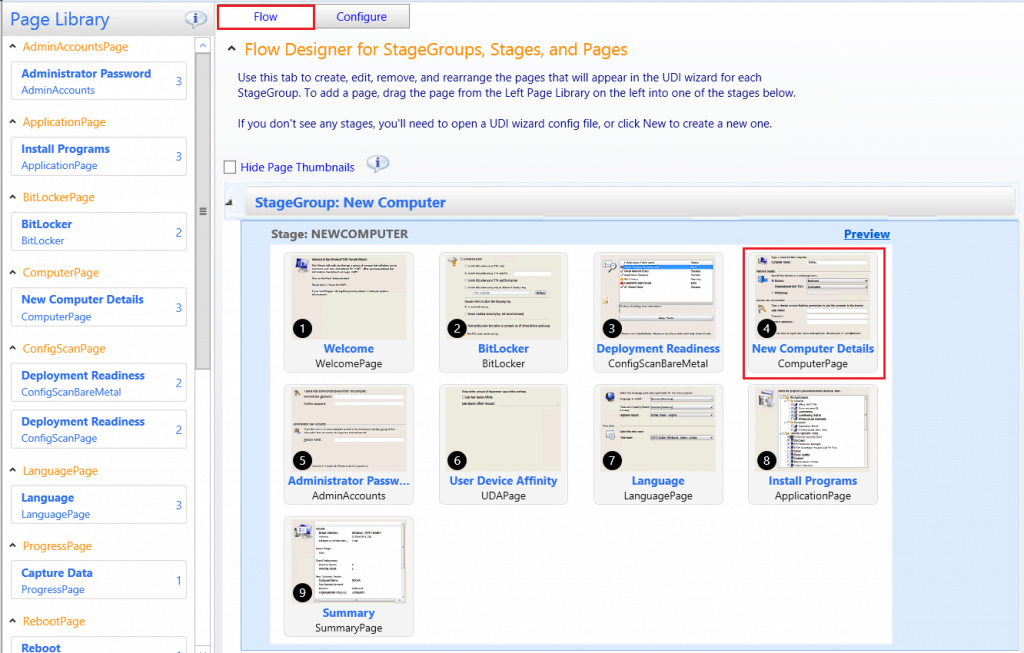
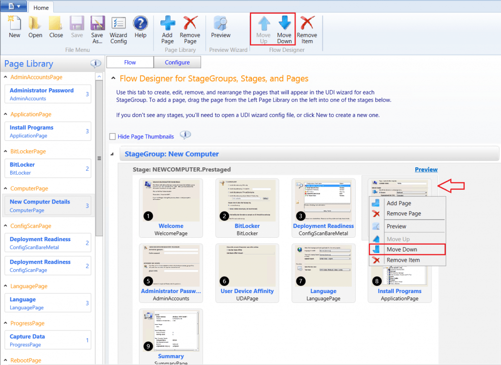
On the Home tab in the Flow Designer group, click one of the following –
- Move Up to make the stage appear earlier in the list of stages within the stage group.
- Move Down to make the stage appear later in the list of stages within the stage group.
The stage moves up or down in the list of stages within the stage group based on the option you select. You can also change the sequence of a stage by right-clicking the stage and then clicking Move Up or Move Down based on the desired result.
Important – Remember to save the UDI Wizard configuration file after making any changes.
To save the UDI Wizard configuration updates
After making the appropriate changes in the UDI Wizard Designer console.
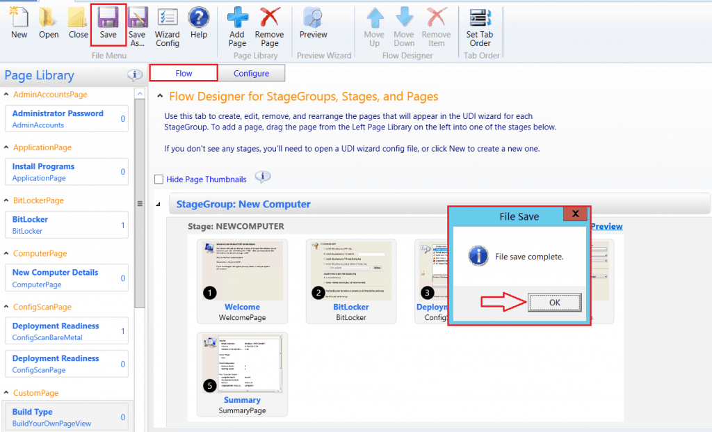
Click Save in the File Menu group in the UDI Wizard Designer console. The File Save dialog box opens, notifying you that the file Save operation is complete. Click OK.
I removed some of the default pages based on requirements.
Preview Wizard Pages and the Wizard Page Sequence Flow
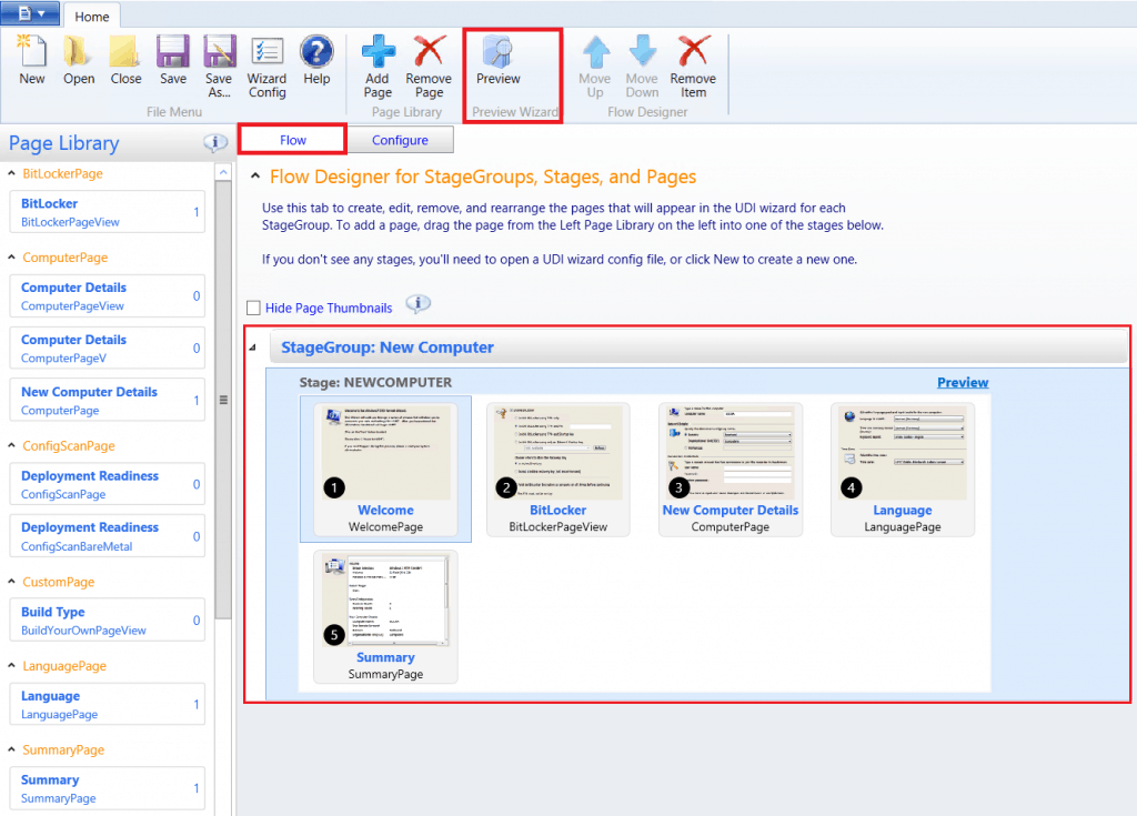
After you have the appropriate wizard pages in the correct sequence for a stage, you can preview how the pages will appear in the UDI Wizard using the Preview feature in the UDI Wizard Designer. The Preview feature allows you to visualize the user experience and to make any changes to the user experience before performing actual deployments.
To preview the wizard pages and wizard page sequence flow for a stage using the UDI Wizard Designer
GUI Mode
In the UDI Wizard Designer console, in the details pane, expand the stage (where the stage is the stage you want to customize).On the Home tab, in the Preview Wizard group, click Preview.
Is UDI Wizard Designer Preview not working in GUI Mode?
If You are using MDT 2013 Update 2, it’s a Known bug. Instead, GUI uses a command prompt for preview.
Command Prompt
- Start to command prompt Run as administrator. [It is always recommended to start execution with admin privilege best experience]
- Go to the MDT Installed directory to locate the OSDSetupWizard utility and type the following command for execution.
<MDT Installed Drive>\Program Files\Microsoft Deployment Toolkit\Templates\Distribution\Tools\x64\OSDSetupWizard.exe" /preview /xml:"<Provide path to XML>"
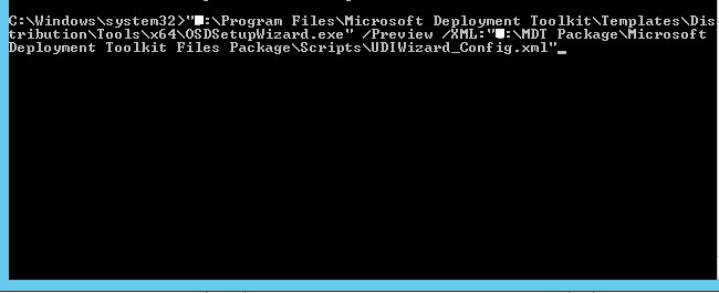
The UDI Wizard opens and allows you to navigate through (preview) the wizard pages. For each wizard page, you can see the controls displayed and whether the controls are enabled.
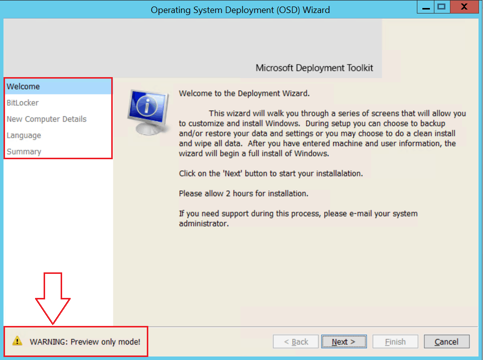
After reviewing the wizard pages, close the UDI Wizard.
Creating Custom UDI Wizard Pages
You can create custom wizard pages that allow you to collect deployment information and the information collected on other UDI Wizard pages. After you create the custom wizard page, you can add controls to it and configure the task sequence variables the controls set.
Important – Make a copy of the SamplePage solution as a starting point.
To create a new custom wizard page, click Add Page on the Home tab. The Add New Page dialog box appears. In the Page Type column, click Build Your Own Page.
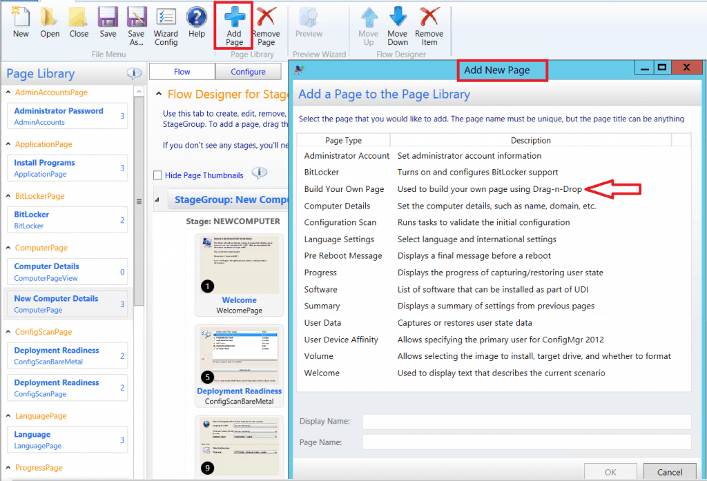
Click on Configure. This will allow placing the desired controls on the form to add customization.
The Build Your Own Page toolbox and empty wizard page are displayed.
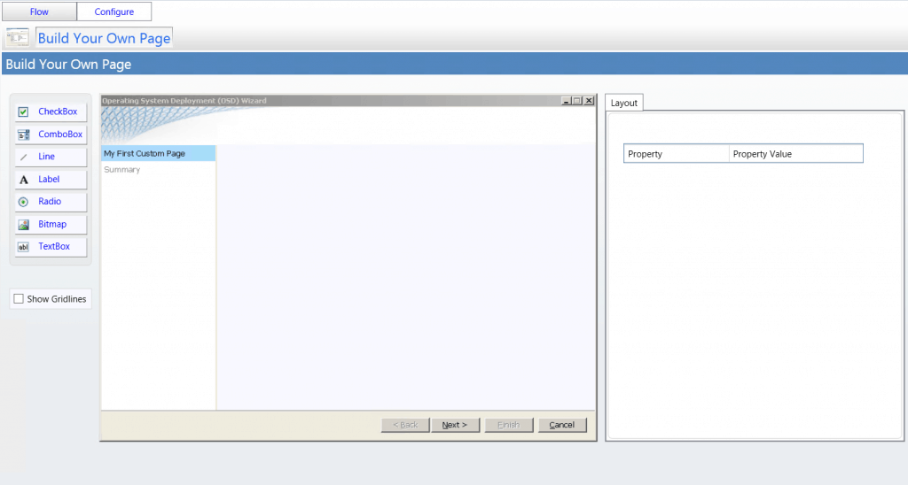
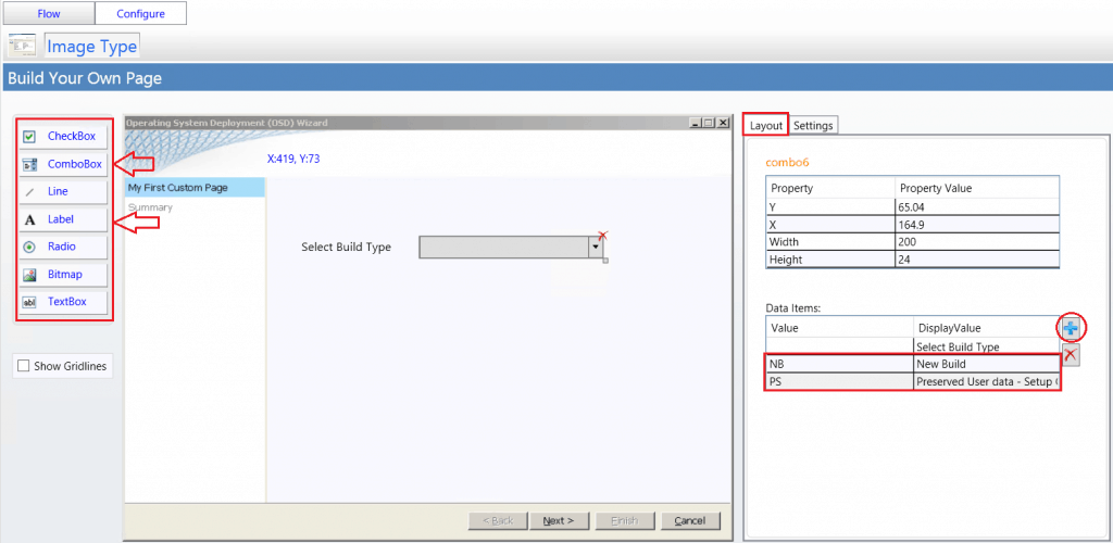
You can add any combination of these controls to your custom wizard page based on the information you want to collect. In addition, you can use the Show Gridlines check box to show or hide gridlines that can be used to assist in visually designing the custom wizard page.
Drag the Label control to the empty wizard page, The Label, ComboBox control is placed on the wizard page and named label….
Note – You use UDI validators to help ensure that the correct information is entered into text fields on wizard pages in the UDI Wizard. When a validator detects an invalid entry in a text box, a message is displayed on the wizard page, and the Next button is disabled until all invalid entries are resolved.
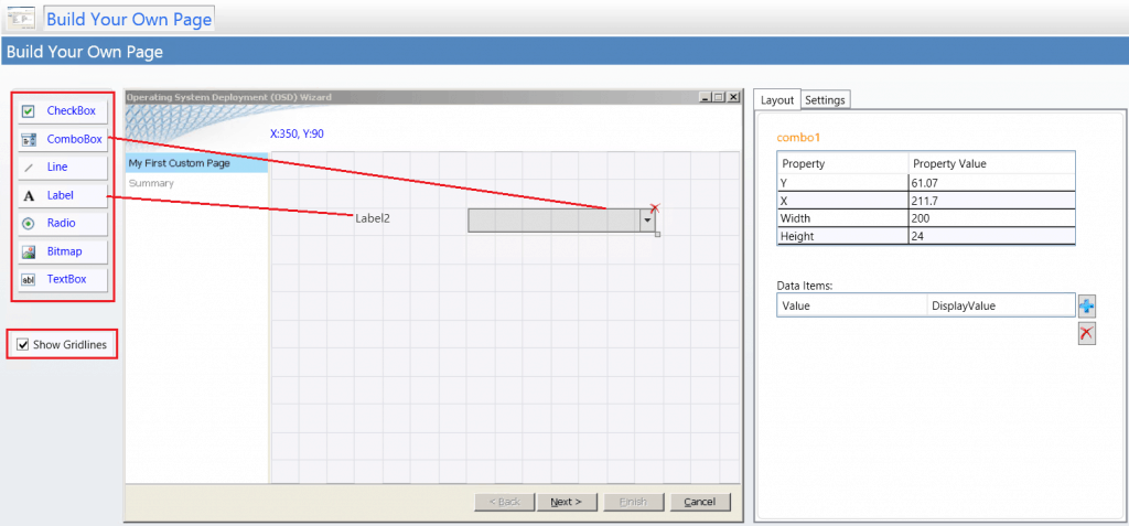
Based on requirements, add data items to the layout properties of ComboBox on the Layout tab. Here, I configured the value to allow users to select the Build Type during task sequence deployment.
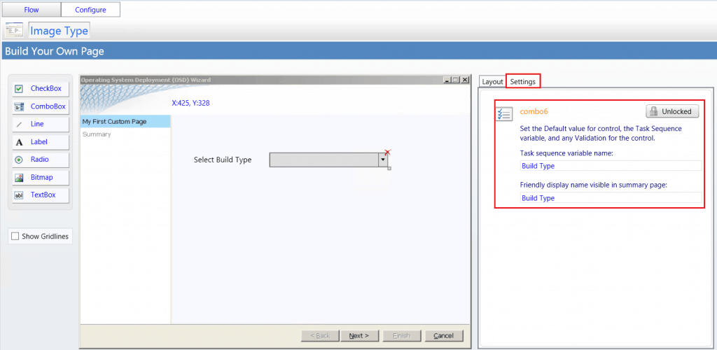
On the Settings tab, configure the ComboBox settings based on your requirements. Once you’ve done this, click Save to the wizard.
In this case, I provided the task sequence variable name—Build Type. This value validates with the Task Sequence Step during execution. If it meets the requirements, the process will be initiated.
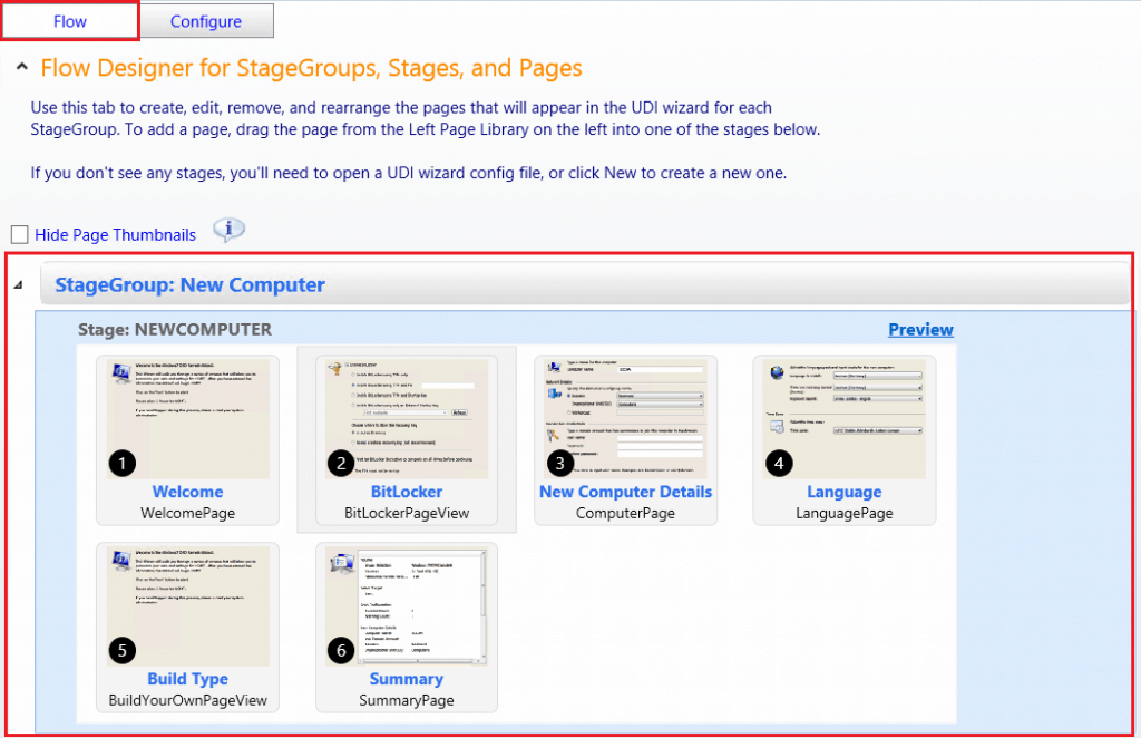
You can add custom wizard pages within a stage and change the wizard page sequence flow based on your requirements. To add a wizard page, click it and then drag it to the location in the stage flow where you want it to appear.
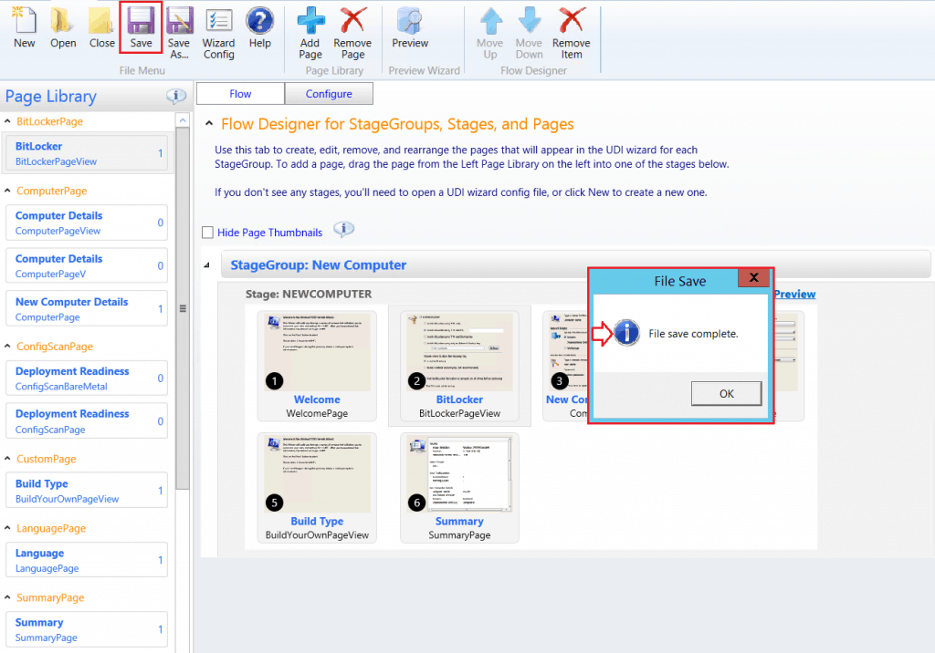
On the Home tab, click Save. The File Save dialog box appears. In the File Save dialog box, click OK. Preview the wizard page flow for a better experience.
Update the Distribution Points for the MDT Package
After making changes every time, you must distribute or Redistribute the content to the distribution point.
Updating the distribution points copies the updated version of the UDIWizard_Config.xml file to the deployment shares specified in the package.
In the Configuration Manager console, in the navigation pane, click Software Library. Go to Overview/Application Management/Packages. Search for packages with your provided name.

Right-click and click Distribute Content. Review the selected content for distribution. Click Next.
Specify the content location and distribute the content to the Distribution point or Distribution point group.
Verify Content Distribution
Before proceeding with deployment, ensure that all the reference sources of Task Sequence are successfully distributed to SCCM DPs.
Customizing UDI Task Sequence to Deploy Image
Use the following procedure to modify an existing task sequence.
In the Configuration Manager console, go to the Software Library workspace, expand Operating Systems, and then select the Task Sequences node.
In the Task Sequence list, select the task sequence that you want to edit. When you edit the Task Sequence, it will look horrible with the number of default steps added.
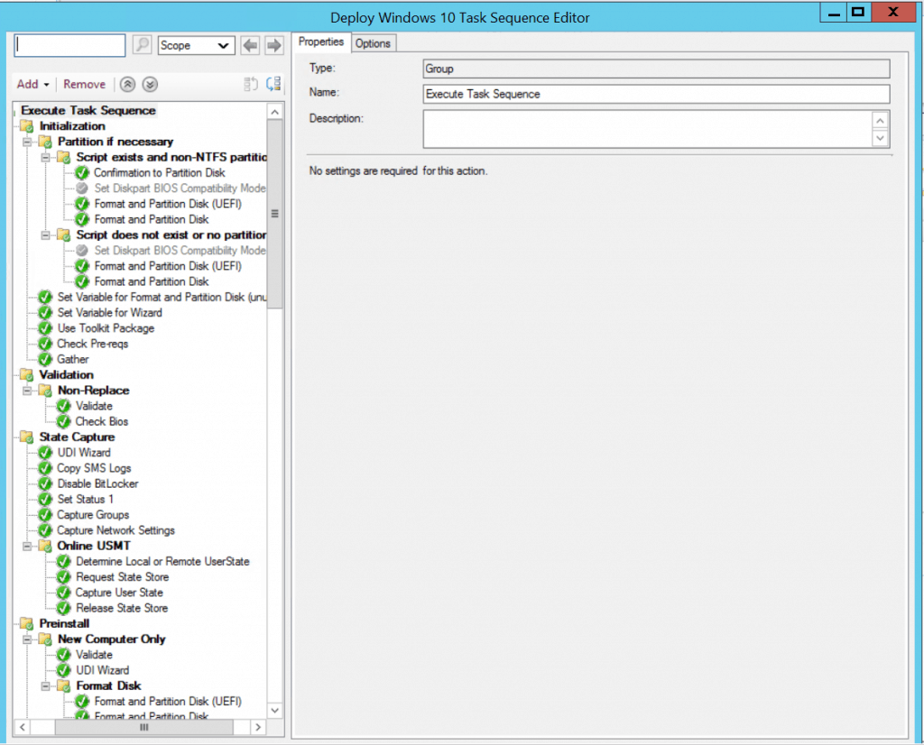
Note – Most of the Task Sequence steps are condition-based and will not run at deployment.
You can add custom Task Sequence Variable steps to proceed with the Domain Join Process and Build Type selection during deployment.
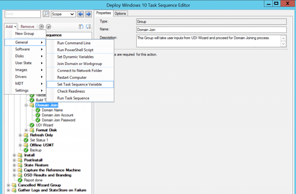
Phase Of The Deployment Process
The Task Sequencer uses these phases to determine which tasks must be completed.
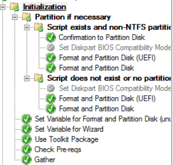
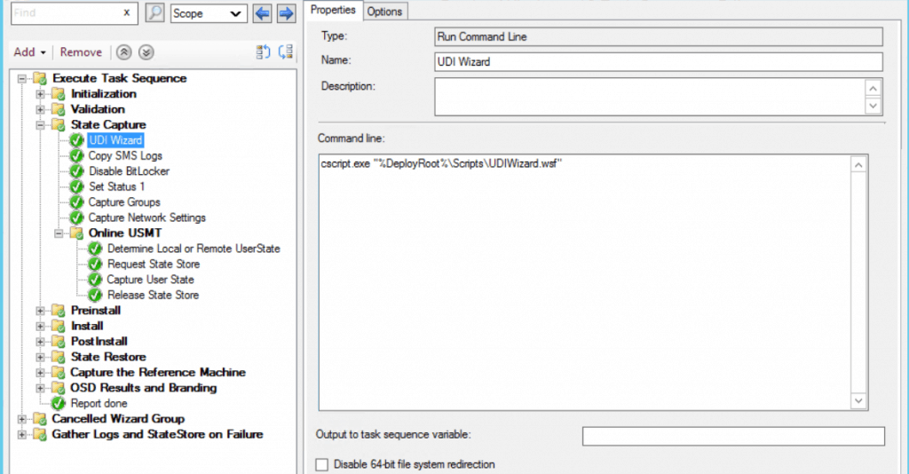
Initialization
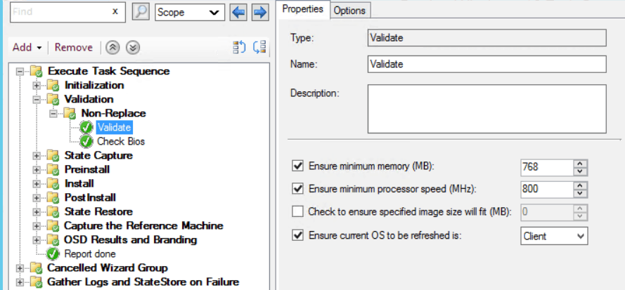
Validation
Identifies that the target computer can run the scripts necessary to complete the deployment process.
State Capture
Saves any user state migration data before deploying the new target operating system.
State Capture - This Group/Step will run if the following conditions are met:
Task Sequence Variable _SMSTSinWinPE equals false

Online USMT - This Group/Step will run if the following conditions are met:
Task Sequence Variable USMTOfflineMigration not equals TRUE
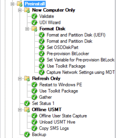
Preinstall
Complete tasks that need to be done before the target operating system is deployed (Format and Partition Disk) using the MDT Toolkit Package.
New Computer Only - This Group/Step will run if the following conditions are met:
Task Sequence Variable _SMSTSinWinPE equals True

Format Disk - This Group/Step will run if the following conditions are met:
If All the conditions are true:
Task Sequence Variable _SMSTSMediaType not equals OEMMedia
Task Sequence OSDDiskPart not equals false

Refresh Only - This Group/Step will run if the following conditions are met:
Task Sequence Variable DeploymentType equals REFRESH

Offline USMT - This Group/Step will run if the following conditions are met:
Task Sequence Variable USMTOfflineMigration equals True
Install
Installs the target operating system.

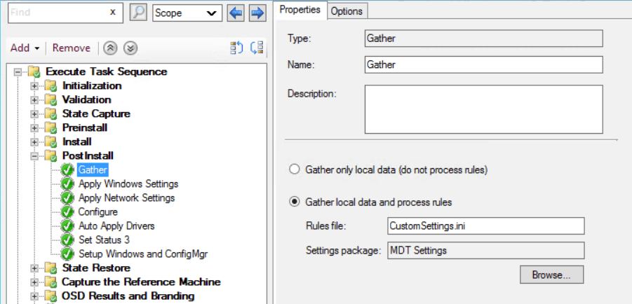
Post Install
Complete tasks that need to be done before restoring the user state migration data. These tasks customize the target operating system before starting the target computer the first time (such as installing updates or applying drivers).
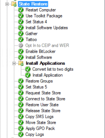
State Restore
Restores the user state migration data saved during the State Capture Phase.
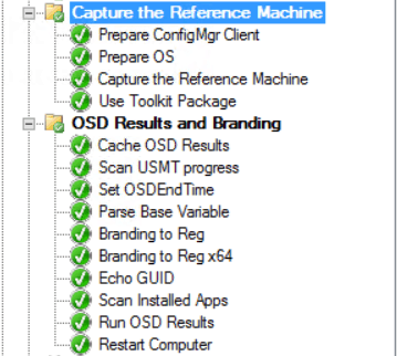
Capture the Reference Machine - This Group/Step will run if the following conditions are met: Task Sequence Variable DoCapture equals YES

OSD Results and Branding - This Group/Step will run if the following conditions are met: If All the conditions are true:
Task Sequence Variable SkipWizard equals NO
Task Sequence Variable DoCapture not equals YES
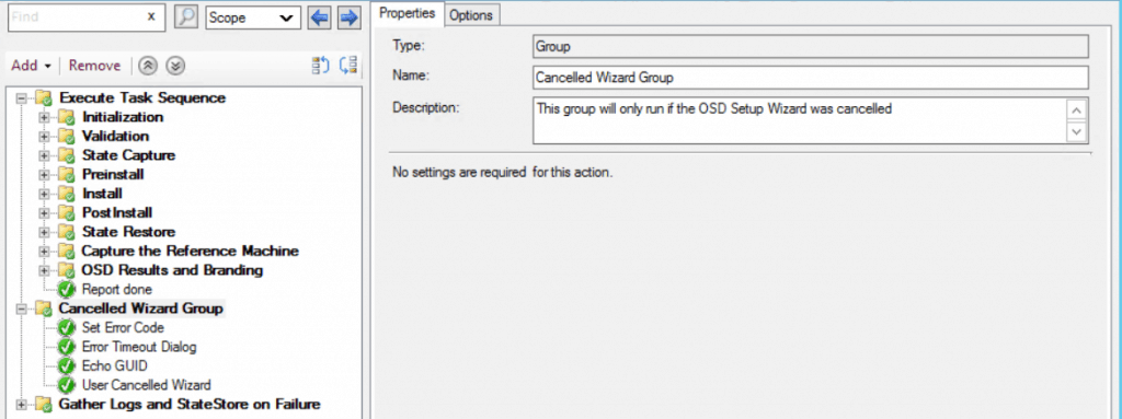
Cancelled Wizard Group - This Group/Step will run if the following conditions are met
Task Sequence Variable OSDSetupWizCancelled equals TRUE
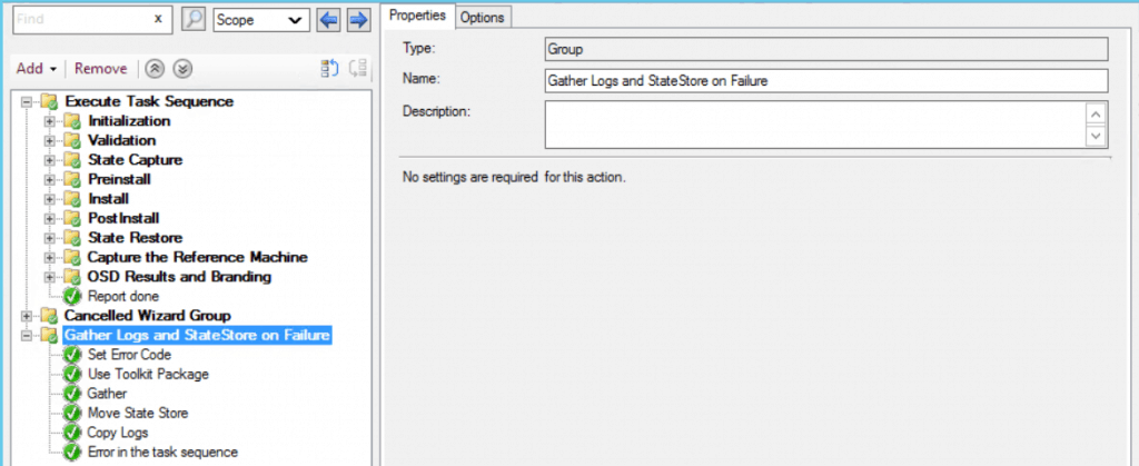
Gather Logs and StateStore on Failure - This Group/Step will run if the following conditions are met:
Task Sequence Variable _SMSTSLastActionSucceeded equals false
Review other settings added in Task Sequence, and make sure to apply all changes. Click Apply and OK, close the window.
Deploy UDI Task Sequence
Select the task sequence that you want to deploy. Right-click and select Deploy.
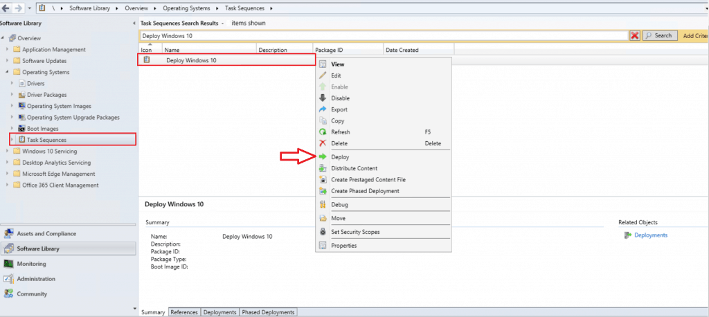
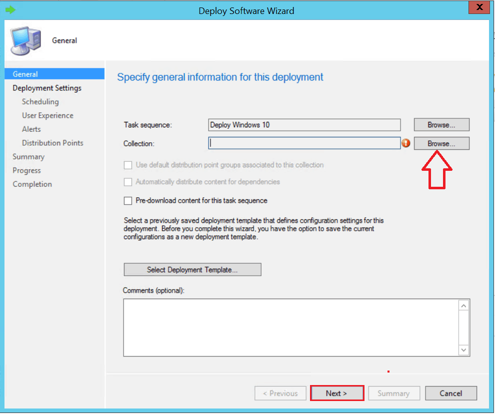
On the General, click Browse to select the collection where you wish to perform the deployment.
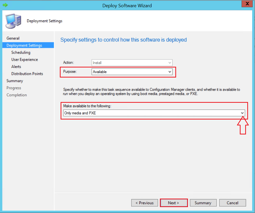
On the Deployment Settings, select the Purpose of the deployment.
Available – Available deployments require that the user is present at the destination computer. A user must press the F12 key to continue the PXE boot process. If a user isn’t present to press F12, the computer boots into the current OS or from the next available boot device.
Required – Required deployments use PXE without any user intervention.
To use a PXE-initiated OS deployment, For the Make available to the following setting, select one of the following options –
- Configuration Manager clients, media, and PXE
- Only media and PXE
- Only media and PXE (hidden)
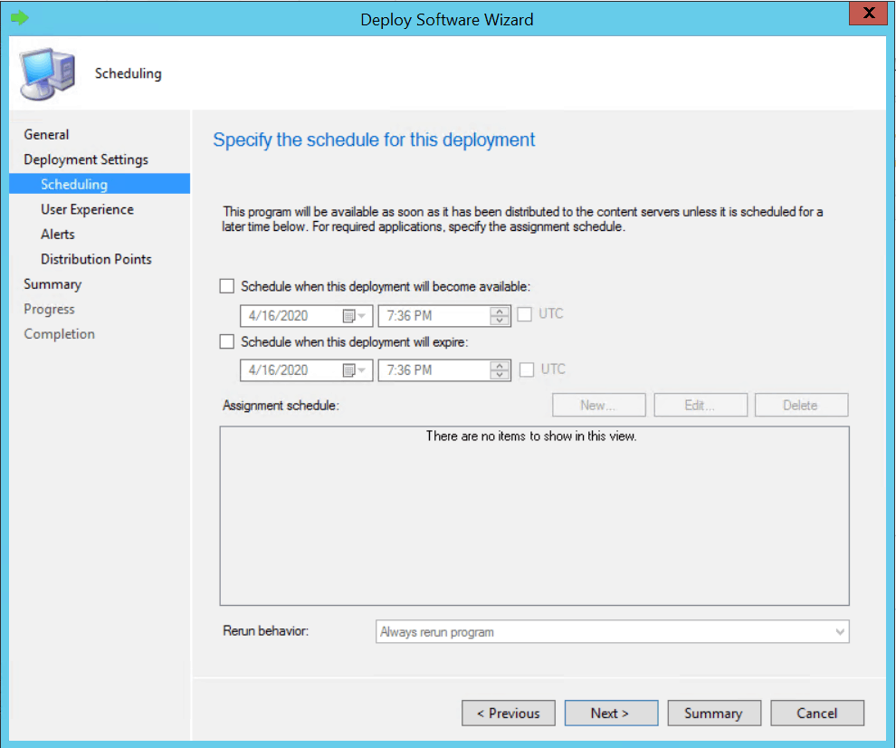
On the Scheduling tab, you can specify the schedule for this deployment.
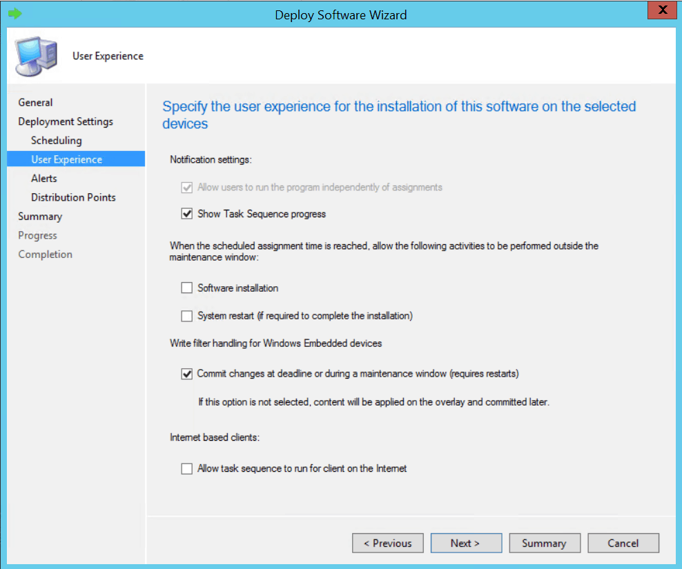
On the User Experience tab, leave the default selected options. Click Next.
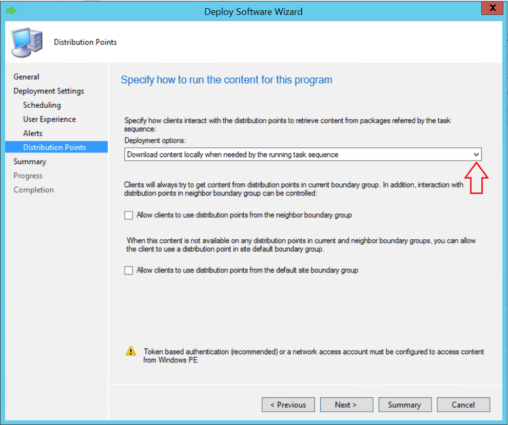
On the Distribution Points page, you can specify how clients interact with the DPs to retrieve content from reference packages. Click Next.
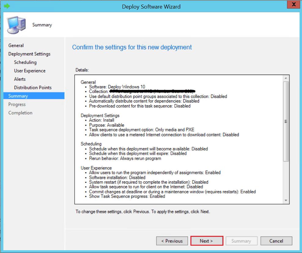
Review the selected options and click Next.
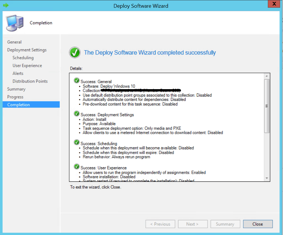
The Deployment of the targeted collection. Close the wizard.
Note – You can redeploy a required PXE deployment by clearing the status of the last PXE deployment assigned to a Configuration Manager collection or a computer.
End-User Experiences
It depends on deployment settings on Target Computers. Press the F12 key to continue the PXE boot process. Windows PE starts, and then the Task Sequence Wizard starts. You will be presented with the Welcome to the Task Sequence Wizard. Click Next.
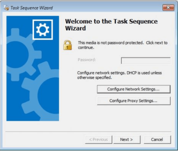
Complete the Task Sequence Wizard by selecting the appropriate UDI-based task sequence. At the appropriate task sequence step, the UDI Wizard starts.
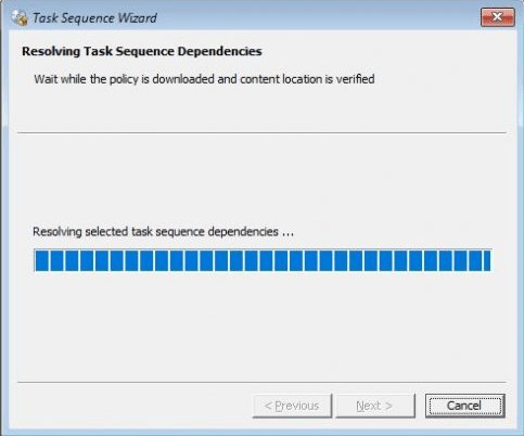
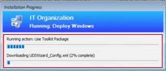
There will be progress bars for the entire Task Sequence and for each step of the Task Sequence.
When the process initiates, it will first download the Toolkit Package, which includes all the required scripts and files to use MDT.
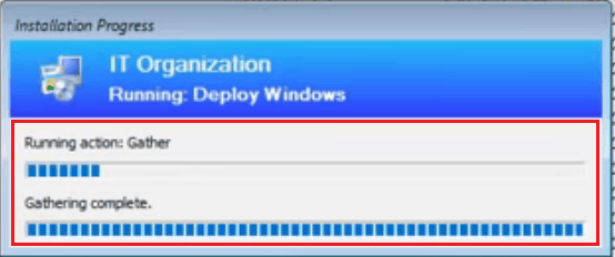
Once the Gather, and Validate phases are completed, you will be prompt with added UDI Wizard pages.
Complete the UDI Wizard based on the wizard pages selected and the sequence of the wizard pages.
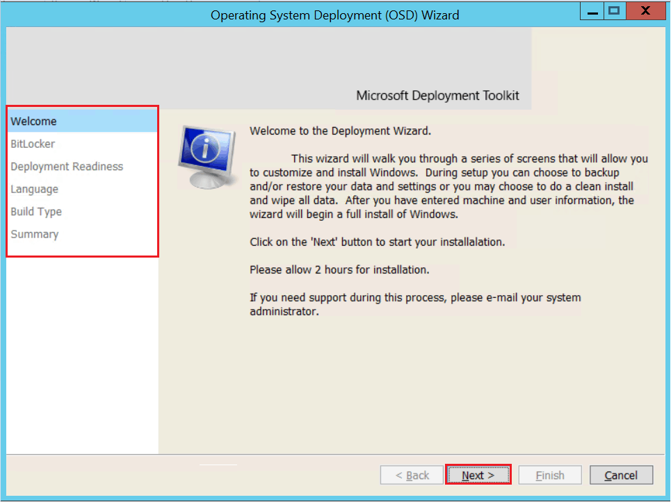
After you complete the UDI Wizard, the deployment of the new operating system begins. When the deployment process is complete, the OSD Results page is displayed just prior to the first user logging on to the target computer.
The most complex post which I tried to finalize in this part! Thank You for taking the long time to read this post. Stay In-Home, Keep Sharing & Learning
Resources
We are on WhatsApp. To get the latest step-by-step guides and news updates, Join our Channel. Click here –HTMD WhatsApp.
Author
Jitesh Kumar has over five years of experience in the IT Industry. He writes and shares his experiences related to Microsoft device management technologies and IT Infrastructure management. His primary focus area is the Windows 10 Deployment solution with Configuration Manager, Microsoft Deployment Toolkit (MDT), and Microsoft Intune.

I am trying to Set an Asset Tag number manually during SCCM TS for our Lenovo ThinkPad machines. Able to add a pane to MDT and ask for the Asset Tag and store it in a variable name ‘TSAssetTag’. This portion works fine during OSD, I am not able to pass the value from the text field e.g. ‘1234’ into the TS. I am not seeing the value from the text field anywhere in smsts.log. The end goal is to set the asset tag value and write to BIOS, I have a command line that I can run. I been looking online and closest articles I see is https://social.technet.microsoft.com/Forums/en-US/b874abfd-3877-4348-8571-6679fc6ede61/using-mdt-custom-input-field-to-set-asset-tag?forum=mdt . We must use a manual entered value from the text field to write to the BIOS only, need to pass the variable that I get from the custom pane. The Code I am using in 2 steps of TS in PS is below. Not sure what i am doing wrong here? Any guidance here would be great, thanks!
1.get Variable TSAssetTag
$tsenv = New-Object -COMObject Microsoft.SMS.TSEnvironment
$tsenv.Value(‘TSAssetTag’) = $TSAssetTag
$LogPath = $tsenv.Value(“_SMSTSLogPath”)
2.\WinAIA64.exe -silent -set “USERASSETDATA.ASSET_NUMBER=$TSAssetTag”
https://docs.microsoft.com/en-us/answers/questions/835453/set-an-asset-tag-number-manually-during-sccm-ts-le.html?childToView=836084#answer-836084
$TSAssetTag = $tsenv.Value(“TSAssetTag”)
Hi, can you use the selection from one page to control what happens on the next page? Example if a checkbox is checked, or a selection from a dropdown is selected, it will decide what options are presented on the following page.